- 您现在的位置:买卖IC网 > Sheet目录311 > AS1113-BSST (ams)IC DRIVER LED 16-CHAN 24-SSOP
�� �
�
�AS1113�
�Datasheet� -� D� e� t� a� i� l� e� d� D� e� s� c� r� i� p� t� i� o� n�
�Detailed� Open-LED� Error� Report�
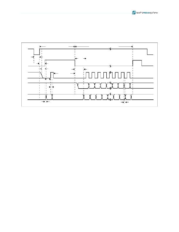
�The� detailed� open-LED� error� report� can� be� read� out� immediately� after� global� error� mode� has� been� run.� SDI� must� be� 1�
�for� the� first� device.�
�Figure� 14.� Detailed� Open-LED� Error� Report� Timing� Diagram�
�OEN�
�Global� Flag� Readout�
�t� TESTING�
�t� H(L)�
�Detailed Error Report Readout�
�LD�
�t� SU(ERROR)�
�t� GSW(ERROR)�
�t� P4�
�CLK�
�t� GSW(ERROR)�
�t� GSW(ERROR)�
�SDI�
�t� SW(ERROR)�
�DBit15�
�DBit14 DBit13 DBit12 DBitn�
�DBit2�
�DBit1�
�DBit0�
�Don’t�
�Care�
�New Data Input�
�SDO�
�T� Flag�
�O� Flag�
�OBit15 OBit14 OBit13 OBit12 OBitn�
�OBit2�
�OBit1�
�OBit0�
�Don’t�
�Care�
�t� P4�
�Open� Error� Report� Output�
�t� P1�
�For� detailed� timing� information� see� Timing� Diagrams� on� page� 9� .�
�Detailed� Open-LED� Error� Report� Example�
�Consider� a� case� where� three� AS1113s� are� cascaded� in� one� chain.� A� 1� indicates� a� LED� is� on,� a� 0� indicates� a� LED� is� off,�
�and� an� X� indicates� an� open� LED.� The� open-LED� test� is� only� applied� to� LEDs� that� are� turned� on.� This� test� is� used� with�
�a� test� pattern� where� all� LEDs� are� on� at� test� time.�
�IC1:[1111111111111111]� IC2:[111XX11111111X11]� IC3:[1111111111111111]�
�IC2� has� three� open� LEDs� switched� on� due� to� input.� 3*16� clock� cycles� are� needed� to� write� the� entire� error� code� out.� The�
�detailed� error� report� would� look� like� this:�
�Input� Data:� 1� 1� 1� 1� 1� 1� 1� 1� 1� 1� 1� 1� 1� 1� 1� 1�
�LED� Status:� 1� 1� 1� 1� 1� 1� 1� 1� 1� 1� 1� 1� 1� 1� 1� 1�
�Failure� Code:� 1� 1� 1� 1� 1� 1� 1� 1� 1� 1� 1� 1� 1� 1� 1� 1�
�1111111111111111�
�1� 1� 1� XX1� 1� 1� 1� 1� 1� 1� 1� X1� 1�
�1110011111111011�
�1111111111111111�
�1111111111111111�
�1111111111111111�
�Comparing� this� report� with� the� input� data� indicates� that� IC2� is� the� device� with� two� open� LEDs� at� position� 4� and� 5� and�
�one� open� LED� at� position� 14.� For� such� a� test� it� is� recommended� to� enter� low-current� diagnostic� mode� first� (see� Low-�
�Current Diagnostic Mode on page 15) to reduce screen flickering.�
�This� test� can� be� used� also� on-the-fly� without� using� an� all� 1s� test� pattern� (see� Figure� 18� on� page� 17)� .�
�Note:� In� an� actual� report� there� are� no� spaces� in� the� output.� LEDs� turned� off� during� test� time� cannot� be� tested� and� will�
�show� a� logic� 1� in� the� detailed� error� report.�
�www.austriamicrosystems.com/LED-Driver-ICs/AS1113�
�Revision� 1.04�
�14� -� 24�
�发布紧急采购,3分钟左右您将得到回复。
相关PDF资料
AS1117-BQFT
IC DRIVER 64LED MOBILE 24-TQFN
AS1118-BQFT
IC DRIVER 64LED W/DELAY 24-TQFN
AS1121B-BQFT
IC DRIVER 16-CH 32-TQFN
AS1122B-BQFT
IC LED DVR 12-CH 24-TQFN
AS1123-BTST
IC LED DVR 16-CH 40MA 24-QSOP
AS1390A-ZQFT
IC BOOST CTLR/BUCK CONV 20-QFN
AS212-L
SOCKET 12V AUTO SAFETY CAP MNT
AS212C
AUTO 12V SOCKET W/SAFETY CAP
相关代理商/技术参数
AS1113BSSU
制造商:AMS 功能描述:IC LED DRIVER CONSTANT CURRENT SSOP24 制造商:AMS 功能描述:IC, LED DRIVER, CONSTANT CURRENT, SSOP24 制造商:AMS 功能描述:IC, LED DRIVER, CONSTANT CURRENT, SSOP24; Topology:Constant Current; No. of Outputs:16; Output Current:50mA; Output Voltage:15V; Driver Case Style:SSOP; Input Voltage Min:3V; Input Voltage Max:5.5V; Dimming Control Type:Analogue ;RoHS Compliant: Yes
AS1113-BSSU
功能描述:LED显示驱动器 RoHS:否 制造商:Micrel 数位数量:5 片段数量: 安装风格:SMD/SMT 封装 / 箱体:PLCC-44 工作电源电压:4.75 V to 11 V 最大电源电流:10 mA 最大工作温度:+ 85 C 最小工作温度:- 40 C 封装:Tube
AS1113CVB
功能描述:AS1113 - Power Management, Power Over Ethernet (POE) Evaluation Board 制造商:akros silicon 系列:- 零件状态:停产 主要用途:电源管理,以太网供电(POE) 嵌入式:- 使用的 IC/零件:AS1113 主要属性:- 辅助属性:过压,热和欠压保护 所含物品:板 标准包装:1
AS1113-XXX-I-A1-D
制造商:未知厂家 制造商全称:未知厂家 功能描述:Analog Filter
AS1113-XXX-I-A1-S
制造商:未知厂家 制造商全称:未知厂家 功能描述:Analog Filter
AS1113-XXX-I-A2-D
制造商:未知厂家 制造商全称:未知厂家 功能描述:Analog Filter
AS1113-XXX-I-A2-S
制造商:未知厂家 制造商全称:未知厂家 功能描述:Analog Filter
AS1113-XXX-I-A3-D
制造商:未知厂家 制造商全称:未知厂家 功能描述:Analog Filter